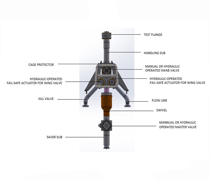
This surface flowhead assembly is an integral part of the Intervention riser string assembly. The unit allows the access to the well bore thru the riser with a variety of wireline and coil tubing tools. It is designed to accommodate coil tubing lift frames and is suspended via 10-3/4” standard casing elevators.
Features
Compact
valve block design for reduced weight and package height.
Includes
two 6-3/8-15K field proven valve.
Includes
two 4-1/16-15K field proven valves.
Includes
a 6-3/8” 10k dynamic swivel assembly per NACE MR-01-75.
Mechanical
Over-ride for valve actuators.
Industry Standards
NAME
DESCRIPTION
REV
API 6A / ISO 10423
Specification for Wellhead and Christmas Tree Equipment (Latest Edition)
20th Edition October 2010
API 17D /ISO 13628-4
Specification for Subsea Wellhead & Christmas Tree Equipment (Latest Edition)
2nd Edition May 2011
API 17G /ISO 13628-7
Petroleum and natural gas industries- Design and operation of Subsea production systems-part 7: Completion / work over riser system
2nd Edition July 2006
SAE AS4059
Aerospace Fluid Power – Cleanliness Classification for Hydraulic Fluid (Latest Edition)
AS4059F September 2013
NACE MR0175 /ISO 15156
Petroleum and natural gas industries- Materials for use in H2S-containing environments in oil and gas production
2nd Edition July 2006
DNVGL-OS-E101
Offshore standards, Drilling facilities
January 2018
Operating Specification
Pressure / Loading Criteria
Specification
Maximum working pressure
15,000 Psi
Maximum Test pressure
22,500
Psi
Load Rating @250°F
1,500,000
lbs @0 psi
Load Rating @250°F
750,
000 lbs @10,000 psi
Temperature / Design Criteria
Specification
Temperature Rating
P+U
Min. Design Temperature
-20° F
Max. Design Temperature
250° F
Nominal bore size
Ø6 3/8”
Drift Dia
Ø 6.34 +.027/-.000
Material Class
EE-NL
PSL Level
PSL-3G
PR Level
2
Well Barrier type
2 x 6 3/8” Hydraulic
gate valve 2 x 4 1/16” Spring-assist fail-safe-closed gate valves
Proven Cut Capability:
None (Can be incorporated if required for Slickline / Braided line /
Electric line in SWAB valve on new equipment)
Operating Criteria
Specification
Water depth
10,000 FT
Service Condition
H2S per NACE MR 01-75
API Monogram
No
Test cap (Top of FH)
10.750-2 ACME-2G Pin
Test cap (Bottom of FH)
10.750-2 ACME-2G RH Pin
Valves and Actuators
S No.
Valves
Nominal Size
Qty
1
Swab valve
6-3/8”
1
2
Lower Master Valve
6-3/8”
1
3
Fail Safe wing valve
4-1/8”
2
Swab Valve
Nominal Size
Ø 6 3/8”
Maximum working pressure
15,000 Psi
Maximum Test pressure
22,500
Psi
Control Pressure
3,000 psi
Max. Control Test
Pressure
4,500 psi
Actuator Type
Double Acting Hydraulic
(Fail As Is)
Position Indicator
Yes
Over-ride
Yes (Separate Assy
supplied with FH assembly)
Lower Master Valve
Nominal Size
Ø 6 3/8”
Maximum working pressure
15,000 Psi
Maximum Test pressure
22,500
Psi
Control Pressure
3,000 psi
Max. Control Test
Pressure
4,500 psi
Actuator Type
Double Acting (Fail As
Is)
Position Indicator
Yes
Over-ride
Yes (Separate Assy
supplied with FH assembly)
Choke / Kill Valve
Nominal Size
Ø 4 1/16
Maximum working pressure
15,000 Psi
Maximum Test pressure
22,500
Psi
Control Pressure
3,000 psi
Max. Control Test
Pressure
4,500 psi
Actuator Type
Fail Safe Close
Position Indicator
Yes
Interfaces
Flow Line
3-1/16”-10K Flange (No X-Overs included)
Kill Line
3-1/16”-10K Flange (No X-Overs included)
Top
10-3/4’’ – 2 ACME-2G BOX (Handling Sub) supplied with 7-1/16-10K API
Test flange